
Machine Tools Syndicate
About us
Home
Contact
Our Client
Products
Sitemap
Infratructure
37 Degree Flare Fittings
Introduction

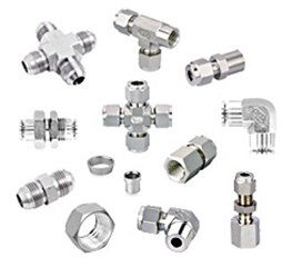
A 37-flare fitting is an excellent pressure fitting having a broad selection of styles & shapes and is very extensively used all over the globe. Main features that call for its use are its simplicity, compactness in design, ease of assembly, high reliability, easy availability & global acceptance. These flare fittings can also be used as hose adapters.

The basic design is simple, which uses a flared tube end to hold & seal the medium under pressure. Main construction consists of three pieces: the body, sleeve & nut. The end of the tube is flared to 74 degrees included angle and held in between the body nose and the sleeve with a nut on top of them, thus resulting in a very effective seal between the fittings and the flared tube.
37 degree-flared fittings are the most commonly used tube connections, internationally. Tube preparation and flaring processes are easily accomplished with either hand or power tools. The large variety of fitting configurations and jump sizes available provide for simplified fabrication requirements and reduced parts count in complex systems
Also these fittings can be easily used in both metric and inch tubing's. One single 37 degree fitting body can take both metric and inch tubes just by change in sleeves. The nuts used are the same, so the cost of the component comes down drastically and also the inventory.
Range :

Ranges of 37 flare fitting manufactured are in between 1/4" to 1 ½" and in metric tubing from 6mm to 38mm.

Features :

The 37 degree flared tube fittings manufactured by us provide leakproof, full flow connections in hydraulic systems operating at working pressures as specified in the tables below.
Thread Size
Working Pressures
Nom Inch Tube O.D. SAE J514 Flared Tube End and SAE J1926/3/ ISO 11926-3 O-Ring Port Thread Size (Notes 1&2) 37 Deg. Flared Tube Ends, Unions and Bulkheads. 37 Deg. Female Swivels.
    MPa psi MPa psi
1/8 5/16-24 UNF 34.5 5,000 34.5 5,000
3/16 3/8-24 UNF 34.5 5,000 34.5 5,000

1/4

7/16-20 UNF

34.5

5,000

31

4,500

5/16

1/2-20 UNF

34.5

5,000

27.5

4,000

3/8

9/16-18 UNF

34.5

5,000

27.5

4,000

1/2

3/4-16 UNF

31

4,500

27.5

4,000

5/8

7/8-14 UNF

24

3,500

21

3,000

3/4

1-1/16-12 UN

24

3,500

21

3,000

7/8

1-3/16-12 UN

21

3,000

17

2,500

1

1-5/16-12 UN

21

3,000

17

2,500

1 1/4

1-5/8-12 UN

17

2,500

14

2,000

1 1/2

1-7/8-12 UN

14

2,000

10.5

1,500

2

2-1/2-12 UN

10.5

1,500

8

1,125

* Threads per SAE J475 Class 2A ext. Class 2B int. (Ref. ISO-263/ISO-R725).
* Unified class 2B threads apply to swivel nuts and with minor diameter modified to class 3B limits for locknuts.

Thread Size
Working Pressures

Nom Inch Pipe O.D.

Dryseal Pipe Thread (NPTF) Male and Female

Fittings With NPTF Pipe Threads


MPa

psi

1/8

1/8-27

34.5

5,000

1/4

1/4-18

27.5

4,000

3/8

3/8-18

21

3,000

1/2

1/2-14

21

3,000

3/4

3/4-14

17

2,500

1

1-11-1/2

14

2,000

1 1/4

1-1/4-11-1/2

8

1,150

1 1/2

1-1/2-11-1/2

7

1,000

2

2-11-1/2

7

1,000

Performance :

Where applicable, fittings are designed and qualified to the requirements of SAE J514. Beaded hose stem ends conform to SAE J1231 and are intended for suction or low pressure lines, typically less than 300 PSI.

Construction :

Stainless steel fittings are machined from 316 stainless steel barstock or forgings. Fittings are passivated followed with machining.

Threads :

Straight Threads :
Internal and external straight threads conform to the Unified National Class 2A and Class 2B Series respectively, with modified minor diameters where specified.

NPTF Threads :
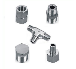
Male and female pipe threads conform to the Dryseal American Standard Taper Pipe Thread (SAE J476a, NPTF) Series which will provide pressure tight joints without the use of a lubricant or sealer. Use of these fittings with non-Dryseal NPT pipe or hose ends is not recommended for high-pressure applications. Note: Where not functionally objectionable, use of a compatible lubricant/sealant is recommended for either NPT or NPTF threads to minimize the possibility of galling in assembly.

Assembly Information :

Tubing for single flare tube ends should be either seamless or welded and drawn, fully annealed tubing per ASTM A213, ASTM A249 or ASTM A269 respectively.

For proper sealing with 37 degree flared fittings, flares for tubing should conform to the requirements of SAE J533. For heavy wall tubing, the optional tube preparation and single flare configuration specified in SAE J533 is also recommended. This optional configuration provides extended sealing surface contact area versus conventional flares.

In the design and fabrication of tubing or hose runs for any hydraulic system, precautions should be taken to allow for sufficient adjustment of the hose or tubing so that proper alignment can be attained at the fitting connections. Improper fit-up or misalignment should be corrected before final connections are made. Location of fitting connections should be planned to maximize accessibility. Whenever possible, use a torque wrench to tighten connections to the recommended installation torque.
Table ST1. Pressure Ratings for 37 Deg. Flared Tube Ends, Unions, Bulkheads and 37 Deg. Female Swivels

Nominal Tube Size

Thread Size

Working Pressures

Nom Inch
Tube O.D.

SAE J514 Flared Tube End and SAE J1926/3/ ISO 11926-3 O-Ring Port Thread Size (Notes 1&2)

37 Deg. Flared Tube Ends, Unions and Bulkheads

37 Deg. Female Swivels


MPa

psi

MPa

psi

1/8

5/16-24 UNF

34.5

5,000

34.5

5,000

3/16

3/8-24 UNF

34.5

5,000

34.5

5,000

1/4

7/16-20 UNF

34.5

5,000

31

4,500

5/16

1/2-20 UNF

34.5

5,000

27.5

4,000

3/8

9/16-18 UNF

34.5

5,000

27.5

4,000

1/2

3/4-16 UNF

31

4,500

27.5

4,000

5/8

7/8-14 UNF

24

3,500

21

3,000

3/4

1-1/16-12 UN

24

3,500

21

3,000

7/8

1-3/16-12 UN

21

3,000

17

2,500

1

1-5/16-12 UN

21

3,000

17

2,500

1 1/4

1-5/8-12 UN

17

2,500

14

2,000

1 1/2

1-7/8-12 UN

14

2,000

10.5

1,500

2

2-1/2-12 UN

10.5

1,500

8

1,125

* Threads per SAE J475 Class 2A ext. Class 2B int. (Ref. ISO-263/ISO-R725).
* Unified class 2B threads apply to swivel nuts and with minor diameter modified to class 3B limits for locknuts.

Table ST2. Pressure Ratings for Fittings With NPTF Pipe Threads

Nominal Pipe Size

Thread Size

Working Pressures

Nom Inch
Tube O.D.

Dryseal Pipe Thread (NPTF1) Male and Female

Fittings With NPTF Pipe Threads

    MPa psi

1/8

1/8-27

34.5

5,000

1/4

1/4-18

27.5

4,000

3/8

3/8-18

21

3,000

1/2

1/2-14

21

3,000

3/4

3/4-14

17

2,500

1

1-11-1/2

14

2,000

1 1/4

1-1/4-11-1/2

8

1,150

1 1/2

1-1/2-11-1/2

7

1,000

2

2-11-1/2

7

1,000

- Contact Us -
MACHINE TOOLS SYNDICATE
Shop No: - 2, Bhanu Housing Co-operative Society,
Khopat, Thane (West), Mumbai: - 400 602..
Tel. No: - +91 22 6526 8721, Fax No: - +91 22 2547 5349.
E-mail: - mts.globe@gmail.com
Website: - www.machinetoolssyndicate.biz
All Trademarks and/or Trade names are the properties of their respective owners
Copyright © Machine Tools Syndicate. All Rights Reserved.